


Published on Apr 02, 2024
Aluminium electrolytic capacitors are widely used in power supply circuitry of electronic equipment as there after several advantages over other types of capacitances. The selection of a capacitor for an application without knowing the basics may result in unreliable performance of the equipment due to expanitor problems. It may lead to customer dissatisfaction and damage market to potential or the image of a reputed company.
The aluminium eletrolytic capacitors are suitable to be used when a great capacitance value is required in a very small size. The volume of an electrolytic capacitor is more than 10 times less than a film one considering the same rated voltage and capacitance. The cost per F is also less when compared with all other capacitors.
An aluminium electrolytic capacitor is composed of high-purity, thin aluminium foil (0.05 to I mm thick) having a dieletric anidation on its surface to prevent current flow in one direction. This outs as anode. Another these two aluminium coils is an electrolytic impregnated paper, which cuts as the dieletric. Since the capacitors is inversely propotional to the dieletric thiclenen. And the dieletric thicknen is propotional to the forming voltage, the relationship between capacitance and cerming voltage is.
Capacitance X Forming Voltage = Constant.
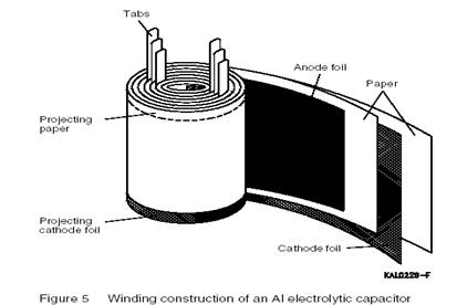
Aluminium tabs attached to the anode and cathode coils act as the positive and negative leads of the capacitor respectively. The entire element is sealed into an aluminium can by using rubber, bakelite or phenolic plastic. The construction of an aluminum electrolytic capacitor is the following:
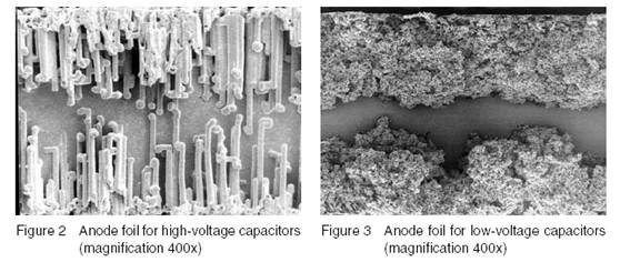
The anode is formed by an aluminium foil of extreme purity. The effective surface area of the coil is greatly enlarged (by a factor upto 200) by electrochemical etching in order to achive the maximum possible capacitance values.
The aluminum foil (A) is covered by a very thin oxidised layer of aluminium oride (O=Al O3. This oxide is obtained by means of an eletro chemical process. The typical value of forming voltage is 1.2 nm/v. the oxide with stands a high electric field strength and it has a high dielectric constant. Aluminium oxide is therefore well suited as a capacitor dieletric in a polar capacitor. The A12O3 has a high insulation resistance for voltages lower than the forming voltage. The oxide layer consistitutes a nonlinear voltage dependent resistance: the current increases more steeply as the voltage increases
The negative electrode is a liquid electrolyte absorbed in a paper. The paper also acts as a spacer between the positive foil carrying the dieletric layer and the opposite Al-foil ( the negative Coil) acting as a contact medium to the eletrolyte. The cathode foil serves as a large contact area for passing current to the operating eletrolyte. Bipolar Al electrolytic capacitors are also available. In this designs both the anode foil and cathode foil are anodized. The cathode foil has the same capacitance rating as the anode foil. This construction allows for operation of direct voltage of either polarity as well as operation of purely alternating voltages. Since it causes internal heating the applied atternating voltage must be kept considerably below the direct voltage rating. Since we have the series connection of two capacitor elements, the total capacitance is equal to only half the individual capacitance value. So compared to polar capacitor, a bipolar capacitor requires upto twice the volume for the same total capacitance.
Rated voltage is the maximum voltage that can be continously applied to the capacitor within specified operating temperature range of the capacitor. The following should be taken into account: In case an AC voltage is super imposed on on a DC Voltage, the sum of the DC voltage and the peak value of AC should not exceed the rated voltage (Vr) of the capacitor. If the DC voltages of both polarities are likely to be encountered in an application, use DC bipolar capacitors. DC bipolar capacitors should not be used for AC applications.
When capacitors are connected is series to achieve a higher operational voltage, the voltage distribution on each of the capacitors will not be the same even for capacitors for same voltage rating. This is due to normal DC leakage distribution.
Surge voltage is the maximum over voltage including DC peak AC and transients to which the capacitor can be subjected for short periods (not exceeding 30 secs every 5 mints). Its value varies between capacitors from different manufacturers and is related to the rated voltage as follows:
Vp = 1.15Vr for capacitors having Vr = 200V
Vp = 1.10 Vr for capacitors having Vr>200V
EQUIVALENT SERIES RESISTANCE (ESR): the ESR is the resistance that the capacitors offers to an alternating current flow. It arises due to resistance from various components including the electrolyte, paper coil etc. the ESR to an alternating current generate heat with an the capacitor. It is specified for 100 Hz at 20C. It decreases with the increase in temperature and frequency.
When the rated voltage is applied to a capacitor, there is initially a high current flow, which exponentially decreases as the capacitor gets charged. Even after the capacitor is fully charged, there will be a constant small value of current flowing into the capacitor. This is formed as the leakage current. It is due to the aluminium oxide which acts as the dielectric. The curve gradient of the exponential current decrease is a measure of the quality of the capacitor. The steeper the curve gradient, the better the capacitor.
The leakage current increases with temperature. After long periods of storage (at a high temperature), the leakage current may exceed the rated value. This is particularly important to check high voltage capacitors, where during the first turn – on, the circuit may trip or, the worst case, cause failure due to increased value of leakage current. Circuit designers should take into account this phenomenon while designing. To bring down the leakage current value, reanodise the capacitor after long periods of storage.
In some applications the required capacitance may not be achieved by using a single Al electrolytic capacitor. This may be the case if:
- The required electrical charge is too high to be stored in a single capacitor,
- The voltages that are to be applied are higher than can be attained by the permissible operating voltage ratings,
- Charge-discharge and ripple current loads would generate more heat than could be safely dissipated by a single capacitor, and
- The requirements on the electrical characteristics (e.g. series resistance, dissipation factor or inductance) are so high that it would be too difficult or even impossible to implement them in a single capacitor. In these cases, banks of capacitors connected in parallel or in series or in combined parallel and series circuits will be used.
| Are you interested in this topic.Then mail to us immediately to get the full report.
email :- contactv2@gmail.com |
